Hello everyone,
I would like to develop a new board. I would like to use the ESP32-WROOM-32E-N4 module.
For a better PCB routing I need to use a different pinout than the LedBox V2 project here.
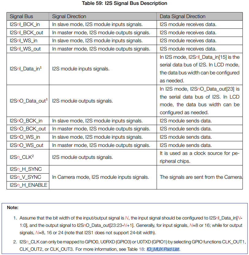
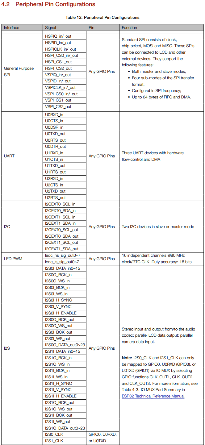
I studied the datasheet and seems that most of the pins can be used. I2C, SPI, I2S hardware can be routed to almost any PIN.
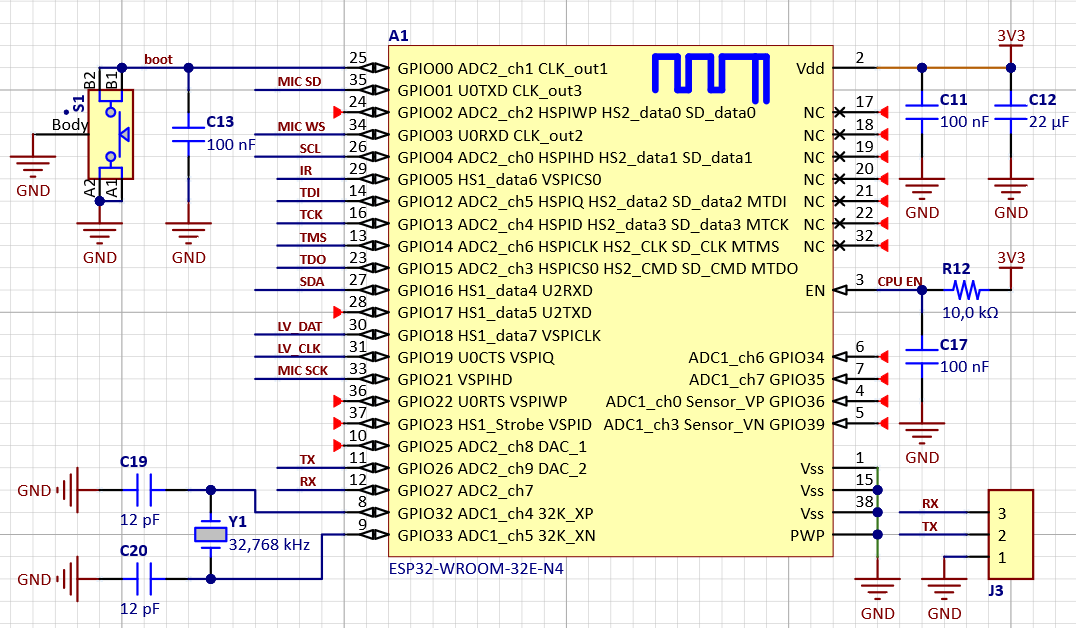
LED strip is connected throught a logic level translator at “LV_DAT” and “LV_CLK”
An I2S microphne is connected on “MIC_” pins
UART is connected at “TX” and “RX” pins
An I2C bus is on “SDA” and “SCL” pins
Could you confirm that I am right so I can proceed with the PCB development and routing?
Please could you also tell me where I what sources I will have to modify? I’m a good low level C developer, but I’m not so confortable with python. ![]()
Thanks!