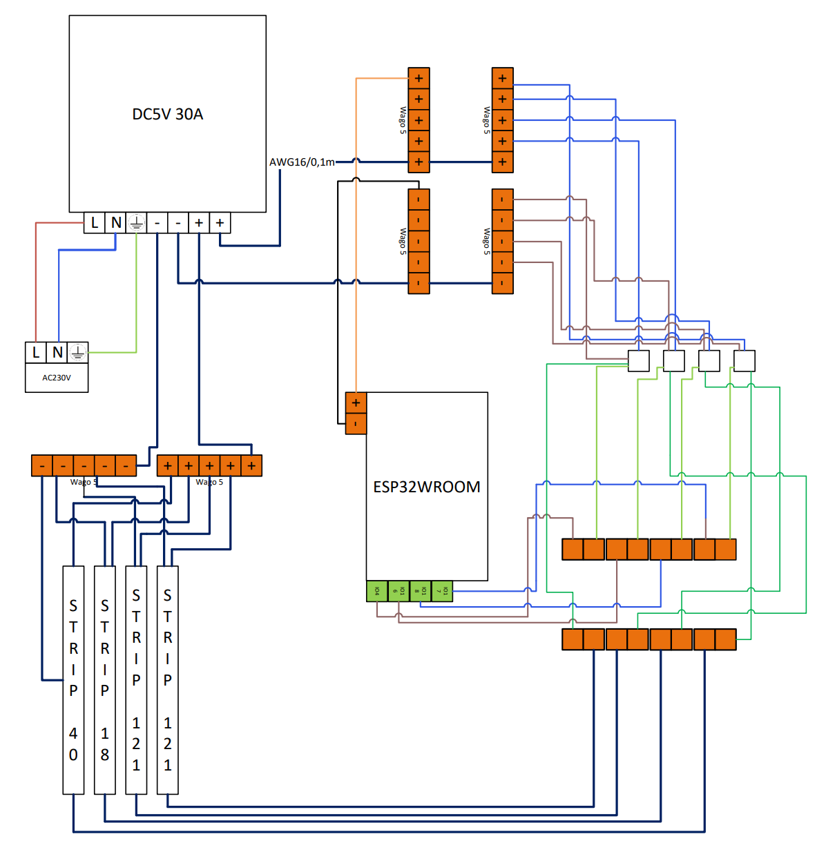
i`m currently building my first setup with the goal to have 4 Stripes (40,18,121/121 LEDs) connected to a ESP32WROOM Devboard.
I’ve been struggling with random flicker in one or multiple stripes. Since then i`ve improved my built and even printed holders for the sacrifice pixels to have them more stable but the problem remains - even if it got better.
With only one stripe everything seems normal but after attaching more, the problem began.
What i have: 5m BTF WS2812B eco already cut to the needed length all wired up with AWG16 wire.
Each channel has a sac. pixel on the dataline in between around 15cm after the GPIO.
I did a lot of resoldering and changing stripes and sacrifice pixels since the beginning. Even a new power supply with 5v/30A (before 5V/5,5A but only for 60 pixels).
The only thing that is really unchanged since the beginning, is the ESP.
So today a new ESP arrives and i will check with that but maybe you can give me a hint if i did anything fundamentally wrong.
I dont see the diode for the sacrificial pixel.
also, this is a high speed signal, not your 50Hz house installation, keep ground loops tight or its very prone to flickering.
yes you need a diode, otherwise its useless. also sacrificial pixel is a poor solution, use a proper shifter.
for loop check wiring diagrams in wled knowledge base.
I would get rid of those sac’ pixels and use a SN74AHCT125 levelshifter. You may also need a resistor on each data line. I could be wrong, but it sounded like you were not too into soldering so this shifter may be a little easier than the bare chip from above: Level Shifters - SN74AHCT125 (Pack of 4) – RGB 2 Go
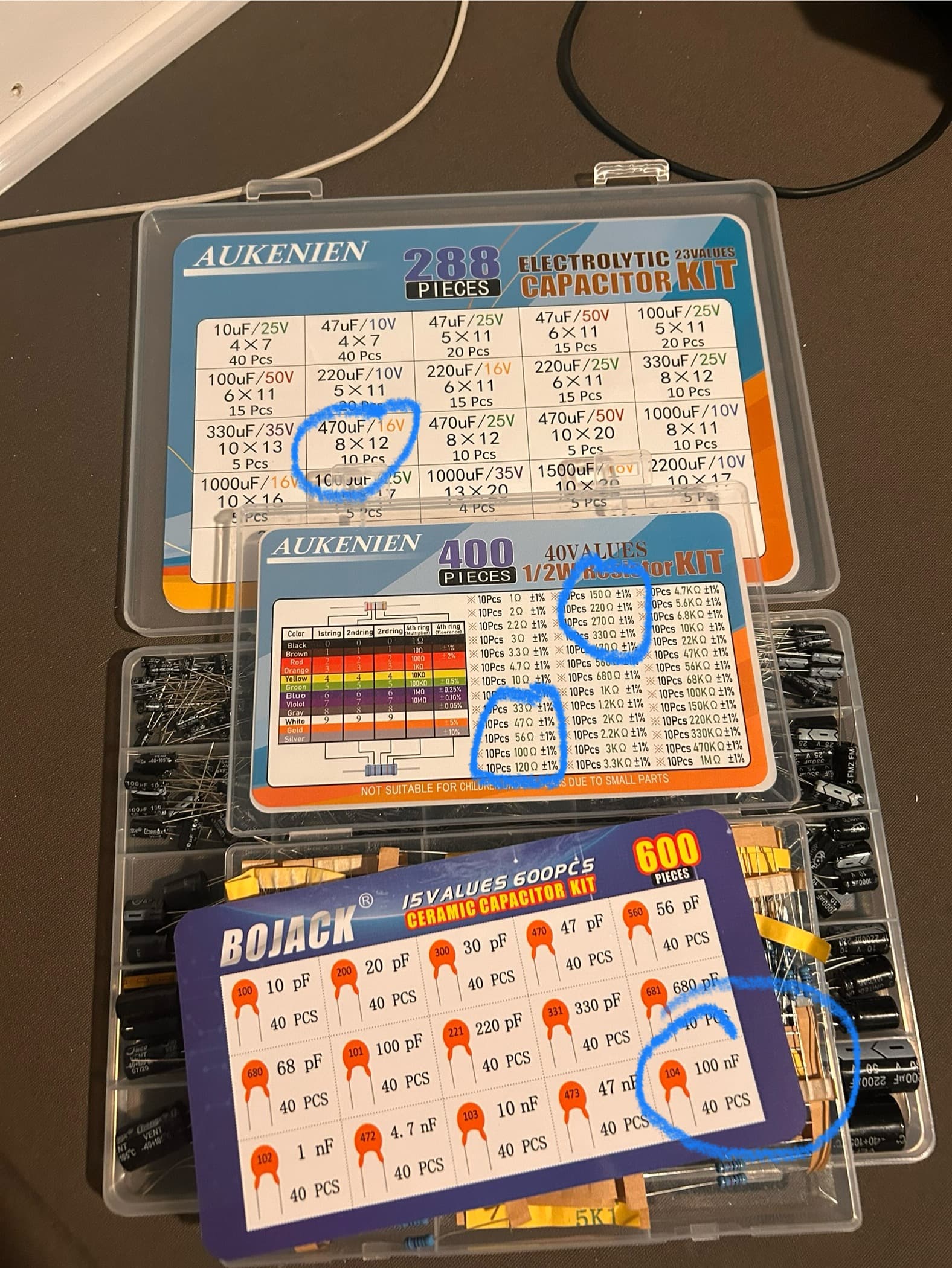
If you are set on using those sac’ pixels I would try adding a resistor after them. What value? That is debatable. Something between 33ohm and 300ohm likely. I would try either 33 or 249
That is the correct levelshifter you linked to. Also note you need the 100nF (.1uF) Ceramic bypass capacitor that is pictured close to the level shifter. -Not sure if that was the capacitor you said you would add, but that one is needed. If you were talking about the 470uF Electrolytic one by the Esp, that one is a good idea for any power dips but is not an absolute needed item.
If you are going to solder the Esp to a prototype board I would use pin header strips, so that if you ever need to remove the Esp it is as simple as unplugging it.
I’m in the USA so navigating that site you are looking to buy from is kinda hard, but I’m talking about these things soldered to the prototype board and the Esp’s pins plugging into them: Pin header kit for Feather, 12-pin and 16-pin socket connectors - buy at BerryBase
I am not sure what you are wanting the screw terminals for when referring to “24v”. Your prior pic shows you have a 5v 30a power supply As for using those screw terminals for the data connections and power to the Esp, they would work fine. *I would not use them for power to your LEDs unless you are sure you will be under whatever their current (amps) rating is.
sorry for the confusion, of course im using a 5v/30Amps power supply. The LED-Stripes will be connected on +/- directly from the power supply via WAGO (AWG16). The 5v power will be delivered to my prototype board via the connectors i mentioned.
Awesome! Looks like you are prepared for your build. 1 tip I would offer would be to triple check that all your connections are correct before connecting power. It can help keep the magic smoke from coming out.