I am running a beginners intro to LED at a Makerspace.
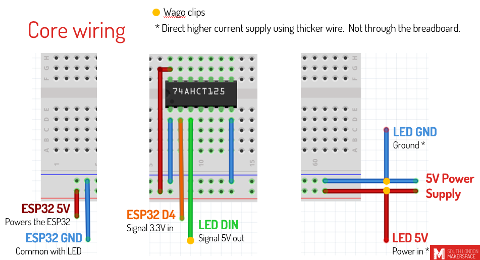
I am using a very basic setup (30 LEDs, 5v 5A power supply, ESP32 and modules on a breadboard, and the higher current items connected using Wago clips. Basically, keep the setup simple, whilst still demonstrating some of the setup for a larger project.
I understand the concept of adding a largish capacitor to the LED part of the circuit to smooth out voltage, but I have some questions:
The capacitor goes between +ve and -ve on the wires running to the LED strip?
How is this implemented when you have power injection along a long strip?
Am I correct that if the wire to the LEDs was much longer, the capacitor would have to be moved to just before the LED?
At what project scale does this become necessary? If only for really large projects, I’ll skip the practical and discuss it in theory only.
If you think I should demonstrate it, can I just connect the capacitor from +ve to -ve between the 2 wago clips? The wire from the wago clip to the beginning of the strip is only 20cm. I don’t want to do any soldering in this course due to time and resource constraints.
The 74AHCT125 needs a ~ 100nF ceramic (not electrolytic) capacitor between its positive and negative supply pins (put as close as possible). It also needs a ~50 ohm (exact value depends on wire) resistor as close as possible to output to suppress ringing and reflections. These are both required and should never be omitted or you will severely decrease the effectiveness of the level shifter.
You can optionally add additional bulk capacitance to the power lines going to the strip. Unlike the above, this is not always necessary, and for a quality power supply with adequate wiring should not be needed (the supply will internally have far more capacitance already), but may help if using a cheap power supply with too little internal capacitance or poor voltage regulation.
Glad to see you are using the levelshifter when demoing this as a maker space. There is far too much poor info from people out there that promote just connecting the data to the gpio direct or ones that use the wrong(i2c) levelshifters.
You may also want to highlight that if people plan to create their projects for a more permanent setup, that they might want to use some proto board and solder their connections. Breadboards stand a much higher chance for bad connections/issues overtime.