24V bus line for longer strip

Hi there,

I’d like to discuss the idea of a 24V bus line that @divsys gave me a few weeks ago on discord issue chat (6.10.23, 00.08).

My project is about indirect light between ceiling and wall. I’d like to install that in every room of my house, so I installed a cable canal (6x4cm) around every room (between ceiling and wall), sk6812-strip (60led/m, 5V) is glued to aluminium profile. The question is/was, how do I provide power and how to inject it, 8m is a minimum of length (1 wled controller), 1 room has something between 30-35m (3-4 controllers). In every edge and further every 2-2,5m (max. alu profile length) I have an injection point either way.
My idea was to put small power supplies like this:
https://www.reichelt.de/led-trafo-40-w-5-v-dc-8000-ma-mw-lpv-60-5-p185799.html
…in cable canal at every injection point. In cable canal runs a 230V-cable which shall be shut off by a relay controlled by wled. First problem was the very high inrush current, relay was damaged several times, even the fuse was blown out some time. I solved that by using industrial relay like this:
https://de.aliexpress.com/item/1005005757882881.html?spm=a2g0o.order_list.order_list_main.16.28105c5fcQ6JTV&gatewayAdapt=glo2deu
…and a inrush limiter like this:
https://www.reichelt.de/einschaltstrombegrenzer-lineare-bauform-16-a-icl-16l-p306701.html

My test installation with 5 power works fine, but has a flash when I turn on light via browser or app. I solved this by using preset/playlist-workaround, but I cannot use this via gui.

Adding a 1000uF capacitor to power line which is recommended here:
https://kno.wled.ge/basics/getting-started/
didn’t make the flash at turn on disappear. It must be something with my power supplies, especially if I get too much of them, 2 power supplies didn’t make that flash.

In this video is said, that you cannot or shouldn’t connect + line of different power supplies. Maybe that is the problem.

I discussed all that in discord issues channel from 5.10.23 11:33 on, some of the experts tried to help me (@blazoncek, @Quindor, @divsys …).

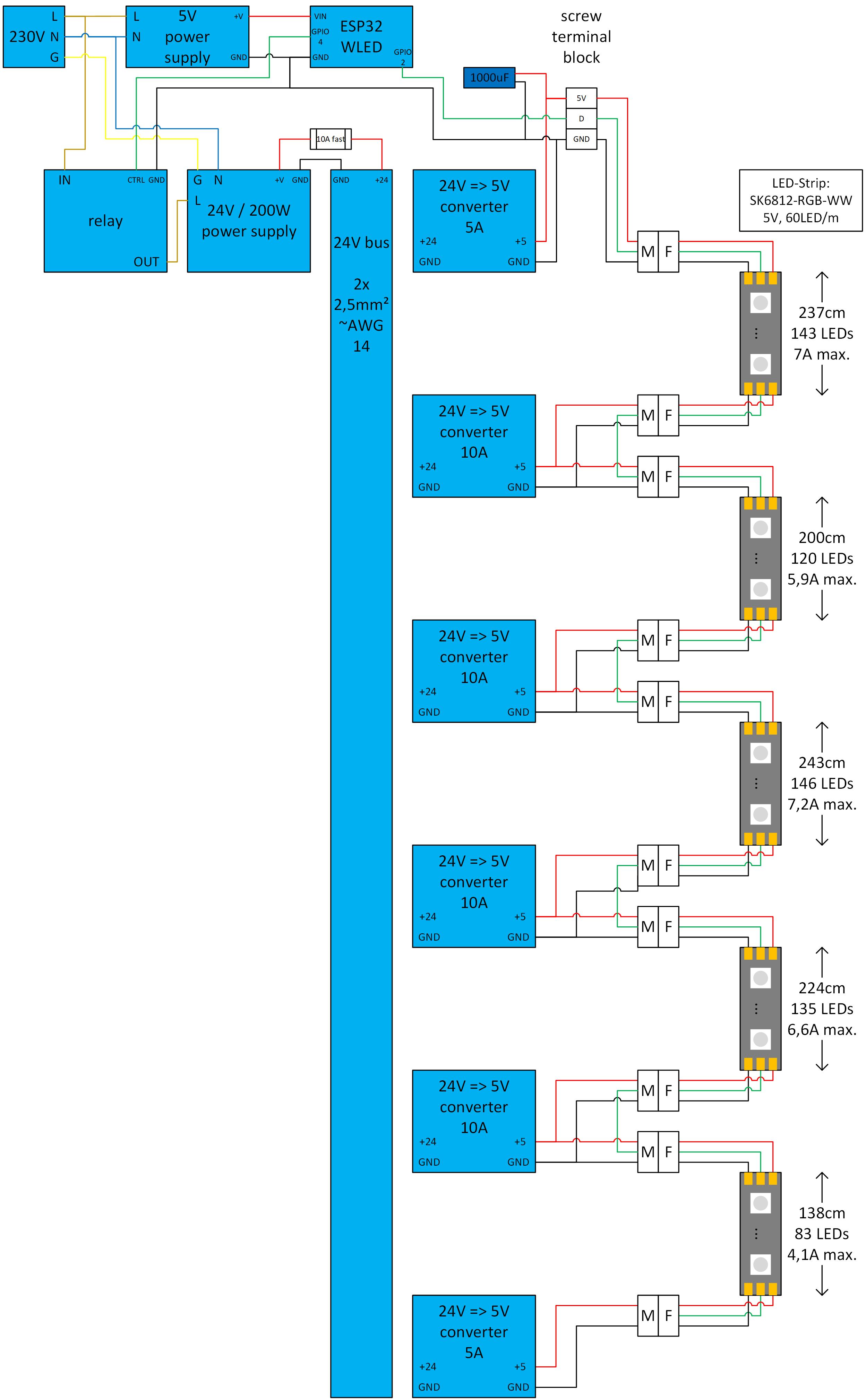
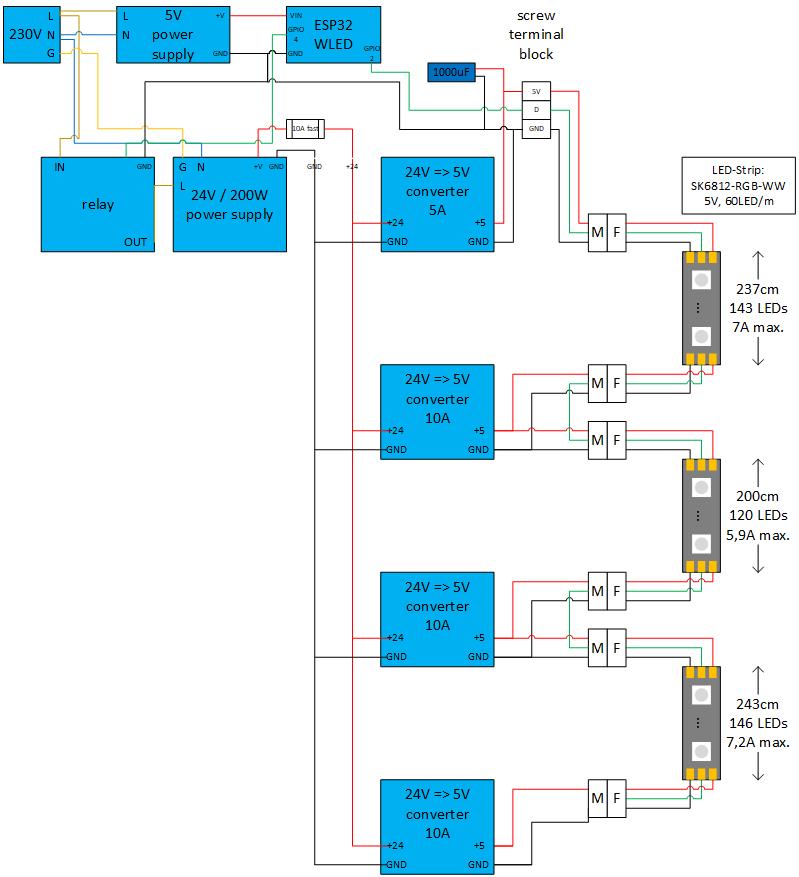
Now comes the idea of @divsys with 24V bus line, which I could use instead of my “power supplies at every injection point” solution. A big 24V power supply at the beginning starts a 24V line, which goes inside cable canal along all the way with the led strip and 24V-to-5V-converter provides the 5V at every injection point.

I have some questions about this 24V line. Maybe someone (e.g. @divsys himself :wink: ) has the answers or further suggestions.

It was said, that voltage drop isn’t a problem. What if I have a strip with 13m or more (15m, 20m) and I “take power” every 2-2.5 meters, won’t the voltage drop be very bad?

How about safety: what fuse have I to take and where to put it? At every injection point or right after power supply at beginning of 24v bus line?

Is this the right converter?
https://de.aliexpress.com/item/4001107349411.html?spm=a2g0o.cart.0.0.55c44ae4oekzK5&mp=1&gatewayAdapt=glo2deu

Is this 24v-bus-line solution scaleable or which limits are there. Does this work?
20m=>1200leds=>300W (60A@5V) or even more?

This is my first post about the flashing problem, if someone wants some details or the suggested solutions to that:

Thanks for bringing this forward so everyone can benefit from the discussion.

Your points:

  1. Voltage drop is always a consideration when trying to power any devices over a longer power line.
    The 3 main factors that determine the amount of voltage drop for your setup are:
    A - Size of wire used, bigger wire handles more current with less drop.
    B - Total current passed through the cable to drive your device(s), twice the current twice the drop
    C - Length of the wire, twice the length, twice the drop.

In your setup, the length of the main power wire is set by the position of the power supply (C is fixed)
You’ve tried multiple injection points, which tries to reduce the amount of current in each injection wire. You’re taking the total needed for the whole strip and dividing it by the number injection wires to (hopefully) give an evenly divided amount on each wire (B)

The last traditional thing to try would be increase the size of the injection wires. If you do some trials with a voltage drop calculator, you’ll find that you need to get some very large wires to handle longer distances with higher currents. They get bulky and expensive, very quickly.

The higher voltage (24V) solution takes advantage of the fact that max power to run your strip is fixed, so at higher voltages you need less current in the same wire. The amount of reduction (before allowing for losses) is just the ratio of the lower voltage to higher or 5/24 - a little less than 1/5.

That means for the same length and size of wire, the 24V drop is (about) 1/5 of the 5V drop. There’s a further benefit as well since voltage drops are measured in absolute volts - .1V, .5V, 1.2V, etc. For a 5V supply, a drop of .8V is 16% and would be considered very high. The same drop for a 24V supply is about 3% and would be considered pretty minimal. And a third benefit is the fact that a 24V->5V converter will be quite happy working at 16V or even 12V (or less), so a 30% voltage drop on a 24V supply is worth noting in your power calculations, but not necessarily a show stopper. On a 5V supply, a 30% drop is typically catastrophic to reliability.

Having said all of this, nothing is free, especially in power transmission. The converters are typically in the 90-96% efficiency range. The voltage drop you will see over the total length of the 24V bus has to be accounted for as well. The net result of those factors is typically a need to oversize the wattage of the 24V supply. I usually use 30% as a rough and ready scale factor. If it doesn’t run the budget up too high, I might increase by 75%.

Fusing is primarily to protect the wire carrying current from the effects of a dead short at the far end.
For buck converter setups, you’ll want to protect the 24V wire for the total current required at 24V. Do that at the power supply end. A purist would say you should also protect the 5V outputs of the converters. For my setups, I prefer to leave out the 5V fuse and keep the converters very close to their injection points (< 5cm) and use the short lighter wires supplied with the converters limiting the maximum current for a 5V short. Additionally the maximum current the 5V convertor will supply is limited.

Short answer, No. Those particular converters are recognized as poor performers at best and completely unreliable at worst. Avoid anything with red lettering and screw terminals.

It’s definitely scalable. The rough calculations for a 300W max power setup, 1200LEDs over 20m:

Total power - 300W=60A@5V, 12.5A@24V.
Calculated worst case voltage drop (24V) (uses - Drop Calculator) of:
18AWG over 20m → ~10.5V
That’s a pretty heavy drop, about 45% leaving only 13.5V at the end of the line.
While that may actually work, it means you’re dissipating 10.5Vx12.5A~132W of power in that line. Over 20m, it probably won’t get particularly warm, but it’s a fair bit of waste power.

If you go up one size to 16AWG wire:
16AWG over 20m → ~6.6V, 28% drop, 17.4V end line voltage.
This is definitely more reasonable, and dissipates ~85W over the 20m length.

And finally:
14AWG over 20m → ~4.1V, 17% drop, 19.9V end line voltage.
This is definitely more reasonable, and dissipates ~52W over the 20m length.

For any of these setups you also have to add an amount of power to the supply to account for converter losses. For 10, 5A converters, I’d add 30W of power to the supply plus the losses calculated for the HV bus. So for the different wiring sizes:

18AWG => 300W+30W+132W=462W or a 500W 24V supply.
16AWG => 300W+30W+85W=415W or a 450W 24V supply.
14AWG => 300W+30W+52W=380W or a 400W 24V supply.

Note, that there’s nothing that stops you doing power injection on the 24V bus, the same way you’d do it on a 5V bus. For the 18AWG example, you’d roughly cut your voltage drop and power losses in 1/2 by running 2 lengths of 18AWG wire to supply the 24V bus. That would give you total power requirements 1/2 way between the 16AWG and 14AWG results.

Thank you very much for your calculations.

Which converters would you suggest?

According to
https://wled-calculator.github.io/
I need max 4.5A at begining/end and 9A in the middle. Because I am bound to room-edges for injection I will need 4.5A convertes in the middle too.

Is this a good converter?
https://de.aliexpress.com/item/1005005114571859.html?spm=a2g0o.productlist.main.87.602e2745ZCw7Dq&algo_pvid=d992032e-7c9b-4405-bd5e-7c8bb7c87d1b&algo_exp_id=d992032e-7c9b-4405-bd5e-7c8bb7c87d1b-43&pdp_npi=4%40dis!EUR!9.99!6.89!!!10.63!!%402101ea8c17008147271546926e75d2!12000031707588842!sea!DE!2270065995!&curPageLogUid=2qYXxVUnkSKq

Is this a good power supply (fits even in my cable canal):
https://de.aliexpress.com/item/1005006012659800.html?spm=a2g0o.productlist.main.9.72d083baOlOmjn&algo_pvid=702c311e-8959-4963-a6d2-2f34d32c8247&aem_p4p_detail=202311240041206466341538080760009452875&algo_exp_id=702c311e-8959-4963-a6d2-2f34d32c8247-4&pdp_npi=4%40dis!EUR!9.34!5.33!!!9.94!!%40210307c117008152807607148e9dbf!12000035335737482!sea!DE!2270065995!&curPageLogUid=hSJKnKgPxldt&search_p4p_id=202311240041206466341538080760009452875_5

I’ve had good success with this supplier:

RCNUN Converters They have a good range of products on their store.

As far as the 24V supplies, those particular slimline are not very efficient. The site even warns about continuous use at more than 50% load so the best you could hope for is 250W. That would make me shy away from those.

I can’t see those converters, because they are not shipping to germany. I try to get them on alibaba.com, but I’m new there.

Any suggestions for power supply?

I will give that 24V-bus-line a try. Seems to be much easier and even cheaper. And maybe, my flashing-problem will disappear :wink:

Have you suggestions for converters which are shipping to germany?

Unfortunately not, I’m in Canada.
Perhaps if you post a note (or do a search) in the German section back on Discord, you can get some first hand information.
The use of 24V supplies and converters is a little advanced, but it’s no big secret (and very useful).

I didn’t catch this topic earlier but I’ve actually done extensive content on exactly this setup a 24v power distribution network with then 5v buck-converters near the injection points, if you have the ability to hide a little buck-conveter block near the strip that’s a great solution!

In my opinion that kind of setup fusing just on the injection lines is good enough, even if the buck-converter fails or after the buck-converter something happens, in theory once it starts drawing a lot of current in any of those conditions, the 24v power distribution line fuse will blow, cutting it all off.

Check out my written article, calculations, diagram and 3 part video series here: 24v power distribution for 5v LEDs - quinled.info . I even have tests on various buck converters although not necessarily in these videos. But of the plastic one’s downrate them a little bit. The 10A will do 8A sustained and the 15A will do 12A sustained. The metal ones generally do a bit better and I’d rate them like 1A below their stated rating.

Thanks quindor, I read your article.

I originally planned to use:

  • 14awg wires to transport 24V
  • 5A converters at beginning/end and if injection points are too close together (1-2m) and 10A converters above 1,8m distance
  • power supply approximately 1/3 above calculated (led at 100% needs 140W => 200W power supply)

Your article advices to use converters 1 step higher than needed (10A at beginning, 15A in the middle)?

Do you have some soggestions for converters which are available today and shipped to germany?

Hi

@divsys
@quindor

I visualized all the details of my first test project with 24V bus in the following draft. Would you mind to give some comments? Thanks in advance.

Description:

  • As I mentioned, I plan to make those projects everywhere in my house (including garden, holiday light…), that’s why I have to scale every detail with factor 10-20.
  • Due to aluminium profile length and room edges I am bound to injection points every 2-2,5m at max, sometimes it’s just one meter or less
  • each male or female connection (M/F) is a 15cm long 3-wired 22AWG cable, so between converter and led-strip there is a 20-30cm cable
  • I calculated the fuse to “10A fast”, because a dead short in the 24V should result 200W/24V=8,3A
  • I would like to cut off the 24V power supply with relay to safe (standby) energy, most of the time there is no light

Special questions:
a) Is the fuse choice right? Is fusing the converter or 5V-site necessary?
b) Should I connect the 5V GND of all converters together?
c) Would that fuse holder (mini version) do it? 14 AWG mini fuse holder

@divsys
I got the converter you recommended from alibaba, 38€ for shipping but still cheaper than other converters at aliexpress. The supplier is planning to open his products in 2024 for germany in aliexpress.

Generally, it looks like a reasonable design, I’m guessing you didn’t show the actual 24V bus->converter connections to keep the diagram “prettier”? As to your specific points:

a) For your 24V supply, choosing a 10A fuse means you’re limiting a 14AWG bus to 10A and can draw no more than 240W from a 200W supply. Those are both good choices IMHO. I agree with Quindor’s earlier comments on NOT fusing the 5V side of the converters.

b) You’ll find that the input and output GND on those converters are already tied together so the 24V bus ground will be common already.

c) That’s a reasonable choice, I’d keep the fuse wires as short as possible and/or go up one size on the wire gauge (12AWG). That helps keep the fuse wiring itself from adding an unecessary voltage drop and leaves you room to expand if you ever want to up size a little.

Glad to hear the shipping options are opening up for Germany. Too bad it’s not until 2024 :frowning_face:
Other comments:

You can drop the 1000uF cap all together, it doesn’t do anything effective in a setup with properly designed clean power to the LEDs.

Those JST M-F connectors are not rated at anything more than 3A. Yes they come with all the strips, but they are intended as data connections not good power connections. I often keep a short (< 8cm) set of lighter (18-20AWG) power wires soldered to the strips and wire the power connections to those. Many people use small terminal blocks or WAGO style connectors. You can even use those spin on wire-nuts if this is an indoor only installation. There are higher power disconnects as well if you really need them.

Note, you can keep the JST connectors using just GND and Data as your data connections, independent of what you do for power. As far as data goes, you haven’t shown what you intend to use as your ESP board and whether or not it includes a levelshifter. Depending on the initial distance to the the 1st LED, a shifter may be critical. You can find them built into many boards, or if you’re planning on putting the MCU more than 5m from the 1st LED, you could use a TxRx differential pair and get the distance handled and levelshift all in one.

What do you mean by “spin on wire-nuts”?
Yes, this is an indoor installation.

I agree, that the JST M-F connectors aren’t the best choice. But soldering 18/20-AWG wires to LED-strip isn’t easy, I will try that again, last time it was a failure. My installation is at ceiling with not much space (6cm), it should be ideally plug&play with less fumbling.

Is there anything like JST M-F connectors with 18awg?

Yes, next update of the diagram shall have the connections.

I designed a board myself, it’s the first shot, I will update it, if the 24V-bus works. No level shifter yet, but I am very close to LEDs, 20-30cm max.

Wire nuts are used by electricians to join wires of varying sizes.
Here, they go by the Trade name “Marrett”

As far as higher power variants of the JST connector, look up “terminal blocks” and you should find a variety. Here’s 2 possibilities:

3-Pole disconnects

12 position terminal blocks

For soldering extension wires directly on the strip:

Make sure everything (including your soldering iron tip) is clean.
Pre-tin the wire you’re trying to connect so when you heat it at the strip, you’re connecting solder to solder.
Use solder with a flux core to improve the flow of the solder.
Try to be patient, if you can do any of the connections on the ground rather than in the air, that’s always easier.

Hello again. Now I installed the test project (a little bit shorter), actually I just changed the power system (230V cable and 5V power supply at every injection) to the 24V-bus.

But I have bad news. The lights are far less stable than before. With 5V PS I had just one colourfull flickering at light up, which I could bypass with the right preset (wait 0,5 seconds till light up). Now I have random flickering with many settings. Unfortunately I cannot upload videos.

I checked the voltage at last injection point, it is 5,03V. I even still have the 1000uF cab. I don’t have the fuse and no level shifter yet.

@divsys
@Quindor

Do you have an idea? What can I try/change next? Why is it now far less stable than with the 5V PS?

Best bet would be to add a proper level shifter.

Power distribution looks like it’s reasonable.

I’d start investigating this as a data problem now.
Start with a proper levelshifter.

I don’t know how long your wires are from the ESP32 to the first part of the LED strip but without a level-shifter and data-resistor it needs to be as short as possible, centimeters basically. And even then it’s outside of the official specifications, it’s more luck if it works properly then “by design”.

I’m much more a fan of using a proper level-shifter setup with data line resistor. With that setup 5m should basically always work and 10m often, beyond that I’d recommend using a differential type solution.

Hello again. I made another circuit board, this time with level shifter and data line resistor. I even have the 1000uF capacitor.

It works, but I sometimes still have a flash during power on.

See the video with super slow mo during power on sequence. Right after the relay triggers (red led turns on) there is first a flash, and after that the actual light setting turns on.

I tried it with and without the 1000uF capacitor, no change.

@divsys
@Quindor
Any ideas?

I don’t know if it helps, here is my board.

On the right side it gets 220V and a small power supply provides 5V for the ESP32 and everything else (besides LED).

On the left side on top the 24V->5V buck converter provides the 5V for the LED. The ground is connected to the other ground (ESP32 etc.). The 5V from the buck converter is only connected to LED. Right next to this “5V-LED-Input” is the 1000uF capacitor (C2).

The level shifter (SN74AHCT125N, U2) is under the ESP32 and on a socket, the ESP32 is plugged in via pin header. There are 2 LED-Data-outs with R1 and R2 as data line resistor. C1 is the 100nF capacitor. Everything is connected exactly like in this article (SN74AHCT125N, two outputs):
https://kno.wled.ge/basics/compatible-hardware/