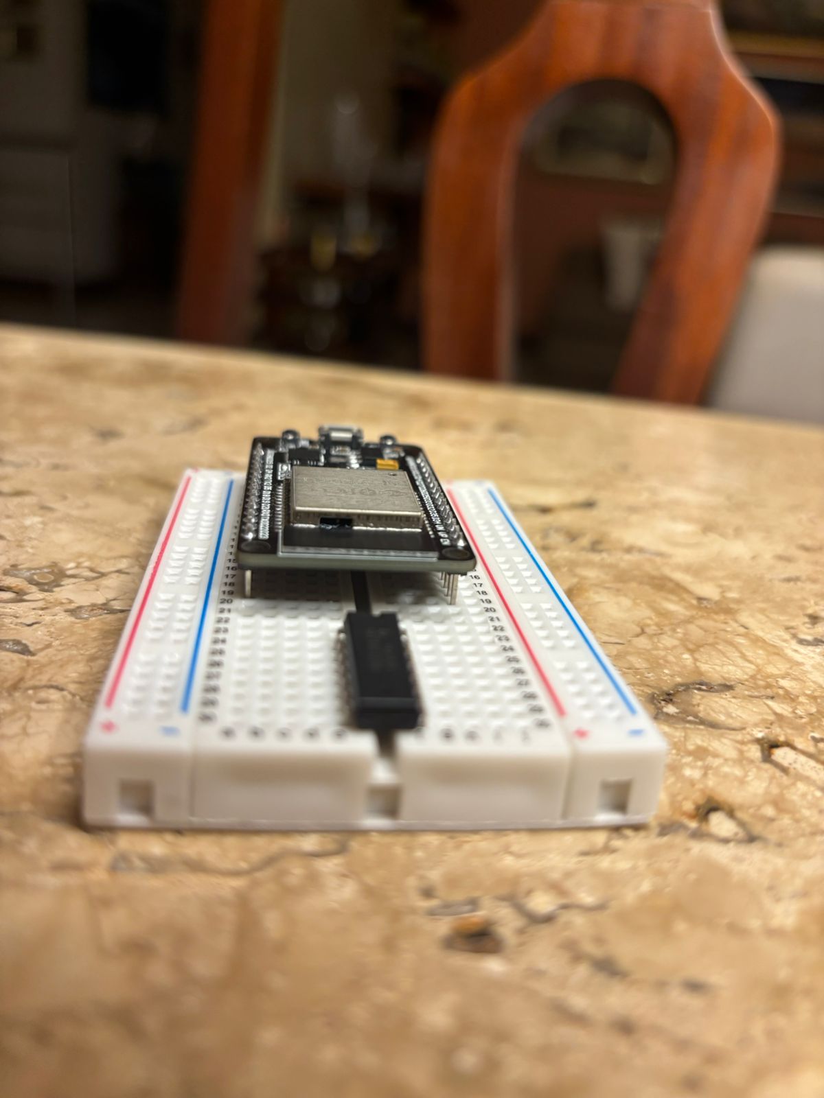
I’ve been fiddling with breadboards to create the recommended circuit for multi-strip, but I realized the standard ESP32 controller I have is a bit too ‘chunky’ for that (I can still insert components on column ‘j’ to the right side, but I have no leftover column on the left side. See photo below). I would still like to use the 400 point breadboard, as I think it has a nice form-factor to it. To that end, is there a slightly smaller ESP32 controller I could use?
If the idea is to use that breadboard as a permanent solution, that is a bad idea. For something temp (or perm) you could look at using a breakout board for the Esp and the breadboard as a temp solution for your other components.
Or if still looking for a narrow version there is the 38pin Esp32 narrow. It is 1 space smaller, giving you a socket on each side on the breadboard.
Again please don’t use a breadboard as a permanent solution as you are very likely to have issues. Don’t even use those DuPont jumper wires in a permanent solution.
I would solder it on prototype board If doing this I would solder female pin headers on to slot the Esp into in case you ever want to remove it/replace it. I would also add a dip socket for the level shifter, again in case you want to remove it. Pin headers and Dip socket optional but makes things ALOT easier for replacement.
or
If soldering is an issue I would try to wire anything I could using wago’s or screw terminals (like offered on the breakout board). A multi port level shifter would be the hard part of that. You would either have to use induvial ones like Quindor’s data booster’s, Falcon F-Amp’s or if you could handle a small bit of soldering you could look at the 4 port shifter from RGB2Go * Actually with that RGB2Go shifter you could likely use JST SM connectors and slide them on the pins, if you rather not solder.
-Soldering would be my preferred solution as it provides the most permanent solid solution. depending on the project and LED choices… I would use solder seal connectors to connect the wires to the pixels
Note: My Amazon links were quick selections. You may be able to find lower cost items with more searching.
Not the best example, but this does show pin headers and a level shifter in a socket. *the screw terminals pictured do not fit that proto’ board without modification.
Understood. @Jinx, would you say it’s a good idea to:
Assemble the circuit using the breadboard to see if everything is working correctly,
Replicate the design using a similar prototype board, soldering the components in place (minus the level shifter and ESP32, which will be attatched to the dip socket and pin headers, which will themselves be sodlered)
It won’t hurt to set it up on the breadboard. It’s hard to say if it would help with a proof of concept, because connections when using breadboards and dupont wires can at times make poor connections and if you see issues when you power up it could very well be due to those less than quality connections (depending on the issue). But if it helps you to visualize things then go for it. There is nothing to lose but your time
The first time I messed with these I did do a crude breadboard sort of setup, but it really did not fully show me that my idea worked, because basically if you wiggled any wires things could/would go wonky.
Most problems people encounter with addressable LEDs are insufficient power to the pixels, not using a level shifter, using data lines that are too long or poor solder connections when using LED strips.
It sounds like you plan to solder to proto board. The easy way is to just solder short wires between the components to complete their connections. Like from the shifter to the Esp’s header pins. Or you can do the much harder way that I do (cuz I’m crazy lol) of having a full solder trace between things. (This can get confusing fast and end up being a hell of a head scratcher to find any error you made)
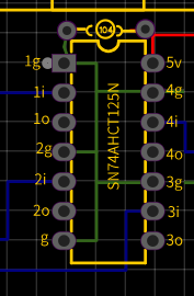
Here is a pic that may be helpful if using a 4 port level shifter like the 74(A)HCT125. I make the common ground connections in between the 2 rows under the chip vs running them all around on the outsides. See the Green lines: