@mike2nl I dod have a BOM pdf file in the “resources” folder .
The difference i had to do, was that, when I plugged in the 3.3v, my FTDI got really hot, and PC would not detect it. This was without plugging into the 12v main power. So I unplugged the 3.3v, and tried plugging in the maine 12v and the PC recognize it on COM3, but wouldn’t program.
I’m using the RX and TX headers marked on the serial, which I believe go through the Level Shifter…Should I try connecting straight to the RX/TX on the ESP-07S?
@OneAn9ryN00b Hi. If you read description to the board it clearly stating that serial is 5V. Most of the people don’t pay attention on logic levels so that is the reason why I did this board 5V TTL.
@srg74 I was plugging into the 3.3v labeled on the I2C header. On the serial, I don’t see any power headers. just two GNDs, two NC’s, and an RX and a TX. Where should i be plugging the 5v from my FTDI?
@OneAn9ryN00b There is no power on serial port for a reason. I want to make sure if it’s a permanent installation and you still need to do some radical updates you not bringing power from serial connector. So on connector you have only TX, RX and Ground. Power up your board check if all power is correct. Disconnect power and then connect only RX, TX and ground from you serial adapter. Short IO0 header with jumper and power a board. Remove IO0 header jumper. Now you should be able to upload your bin file.
@srg74 No go, same error: Timed out waiting for packet header
@OneAn9ryN00b Please give me chance I will tested and give you answers ASAP. I’m not on quarantine so have to work.
Looks like you found my error. I will take a look closer. Thank you
First looks like a well done controller. I am looking over the v0.8 materials.
Can you or anyone give a rough sketch as to how this controler is connected
to a set of LEDs just to blow the cobwebs out of my head
Thanks in advance
Mike
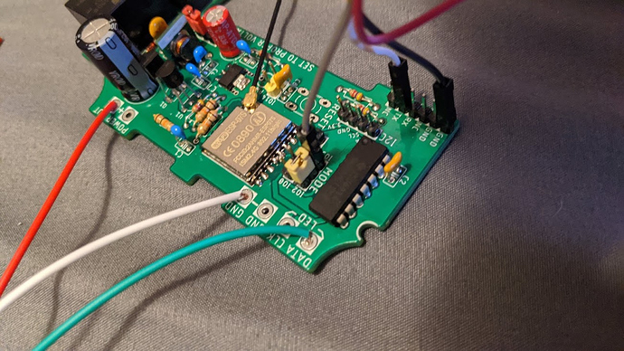
Noting special. Controller working with addressable LEDs. So power wires soldered to power pads and data to data pads. There is a photo with inner connections visible Controller-for-WLED-firmware/controller.jpg at master · srg74/Controller-for-WLED-firmware · GitHub
